| VIEW | 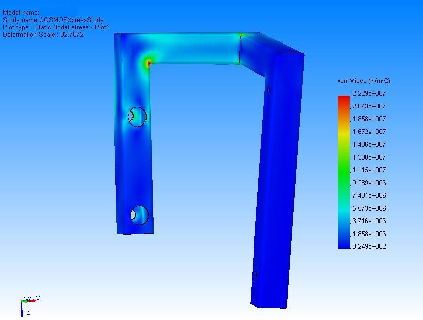 |
| Model name: | Sample Two |
| Model location: | C:\INED website |
| Results location: | C:\INED website |
| Study name: | Sample Two |
| No. | Part Name | Material | Mass | Volume |
|---|---|---|---|---|
| 1 | Sample Two | 6061 Alloy | 0.205314 kg | 7.60424e-005 m^3 |
| Restraint1 <Sample Two> | on 2 Face(s) immovable (no translation). |
| Description: |
| Load1 <Sample Two> | on 2 Face(s) apply force 3 lb normal to reference plane Front using uniform distribution |
| Description: |
| Mesh Type | Solid mesh |
| Mesher Used: | Standard |
| Automatic Transition: | Off |
| Include Mesh Controls: | On |
| Smooth Surface: | On |
| Jacobian Check: | 4 Points |
| Element Size: | 4.2379 mm |
| Tolerance: | 0.2119 mm |
| Quality: | High |
| Number of elements: | 18251 |
| Number of nodes: | 36545 |
| Quality: | High |
| Solver Type: | FFE |
| Name | Type | Min | Location | Max | Location | ||||||||
|---|---|---|---|---|---|---|---|---|---|---|---|---|---|
| Plot1 | VON: von Mises stress |
|
|
|
|
| JPEG | ||
|---|---|---|
|
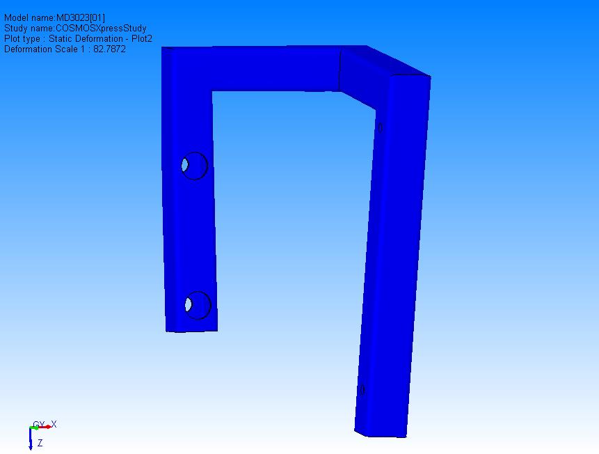
| Plot No. | Scale Factor |
|---|---|
| 1 | 82.787 |
| JPEG | ||
|---|---|---|
|
| JPEG | ||
|---|---|---|
|
| Material name: | 6061 Alloy |
| Description: | |
| Material Source: | Library files |
| Material Library Name: | coswkmat.lib |
| Material Model Type: | Linear Elastic Isotropic |
| Unit system: | SI |
| Property Name | Value |
|---|---|
| Elastic modulus | 6.9e+010 N/m^2 |
| Poisson's ratio | 0.33 |
| Yield strength | 5.5149e+007 N/m^2 |
| Mass density | 2700 kg/m^3 |